How To Make A Rotating Fly Sparge Arm For All Grain Brewing
Ever since I started brewing all grain beer, I’ve wanted one of those cool rotating fly sparge arms. They revolve around and distribute water on your grain bed so all the precious sugars are washed from the grains. There are two schools of thought; the first being don’t use it and just keep an inch of water on top of your grain bed and the other is better efficiency when fly sparging over a longer period of time. Whichever you prescribe to; this is a cool little project! Read on and I’ll show you how to make a DIY rotating sparge arm.
All of the materials can be found at a general hardware store, hobby store or craft store. Everything should cost under $10 dollars. I even found an online hobby stores that sell everything for less than $6 dollars plus $4 dollars shipping and handling. I recommend going to the store and trying the pieces together.
The basic premise is you want the 7/32” tube to fit snug, but turn freely in the 3/16” tube. The 3/16” tube will fit into the 1/4″ tube with the 4 O-Rings and should be held together tight. The design works flawlessly, but you need time and patience.
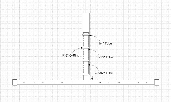
Build Of Materials
1 X K&S Engineering Round Brass Tube 7/32” x .014 (Stock #130)
1 X K&S Engineering Round Brass Tube 3/16” x .014 (Stock #137)
1 X K&S Engineering Round Brass Tube 1/4” x .014 (Stock #131)
4 X Rubber O-Rings that fit around 7/32” tube and fit tight into the 1/4” tube
2 X Rubber O-Rings that fit around 1/4″ tube
2 X 3/16” plastic bolt covers
1 X 18” Board of wood
Tools Needed
A drill and assorted drill bits
A Dremel (it helps to have one)
Solder (thin electrical solder)
Plumber’s flux paste
A plumber’s torch
A tubing cutter
An auto center punch
Some vice grips or something to hold the tube together that can stand heat
Some chapstick or Vaseline
Sand paper
Steps
Take the 7/32” tube and cut it into a 3” piece and a 9” piece. Be exact on the 9” piece, because this will become the fly arm and you will want to keep it balanced.
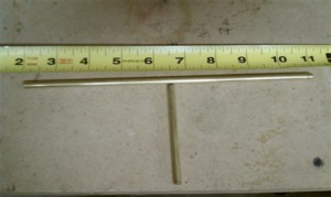
Lay the 9” piece against the tape measure and score it lightly 4 1/2″ in, then take the center punch and set the spot for drilling.

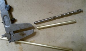
Drill a hole 1/2 the size of the tube diameter in the middle of the 9” piece of 7/32” stock as a pilot hole. Then select a drill bit a little smaller than 7/32” of an inch. I used a caliper, but you can just match it up. The key here is you can always take more metal off, you can never put metal back. You will want the 3” piece of 7/32” stock to fit snug in the hole. If you own a Dremel start using it now and finesse the hole larger while checking it every step of the way.
Sand both the 3” 7/32” stock and the 9” 7/32” stock and prep it with plumber’s flux.
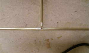
Now for the hard part: make sure the 3” stock is at a perfect right angle and it just pushes in far enough to cover the sides, but not all the way as it will restrict flow of water. Heat the tubes with the torch and make sure it does not move in the jig. Then gently apply the solder, just using the resonant heat from the pipes. Not too much solder! Just enough solder to fit and keep it together, but not enough that it puddles inside the tube. Remember it needs to allow for flow and be balanced in the end.
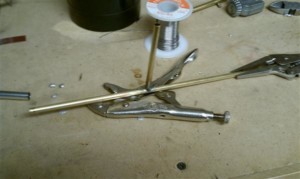
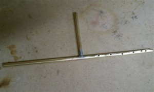
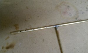
Now drill holes on the right side 1” from center and every 3/4″ then double up on the end at 1/2″ and 1/4″. The ends should have a lot of flow compared to the middle; this will help propel it around. Use a 1/32” or 1/16” drill bit to make the holes. Then flip it and do the same on the other side. Make sure you have hole on opposite sides as this will be how it propels itself around; just like a garden sprinkler.
Cut the end caps if they are really long and put them on the ends, however later this is how you can balance the arm so don’t cut too much!
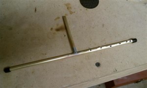
Next take the 3/16” stock and cut it at 2 1/2″ inches. If you are using a tubing cutter, it will knurl the end and make it smaller. Use a drill bit and sand paper to make it true again and make sure it floats on the 7/32” stock.
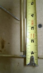
Fit the 3/16” stock over the 3” stub of 7/32” fly arm and gently expand the 7/32” tube so the 3/16” tube doesn’t come off. I used a small drill bit and put it inside and slowly started running it around the inside to smash it out. Later I found out I had some high spots, so I used rubbing compound to smooth it out. This part took a lot of jerking around to make sure it spun smooth.
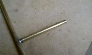
Once it spins freely with the weight of the arm hanging on it, put the four O-Rings on. Lube the outside of the O-Rings up with chapstick or Vaseline, just the outside of the O-Rings. Then get ready to insert it into the 1/4” tube.

Push it in snuging the O-Rings into the tube and press it together until the 3/16” tube is flush with the 1/4″ tube.
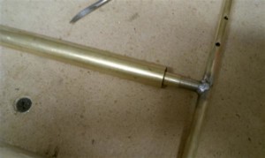
Drill a 1/4″ hole centered into the piece of 18” wood. Then place the O-Rings on the completed sparge arm to adjust height.
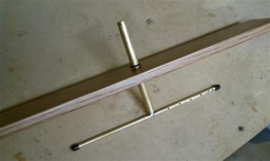
Notes
You can further trim the 1/4″ tube down; I cut mine down to 5”.
You may need to neck the 1/4″ tube up to 3/8” or 1/2″, just use 1” pieces of hose to do so.
If you like this article… Please take a moment to visit one of my sponsors, that keep this site going.
Final Product
October 17th, 2010 at 11:51 am
Why don’t you use a “T” instead of punching and drilling a hole?
October 17th, 2010 at 12:09 pm
I had plans to make one with a T and even went out and purchases all the pieces… I used a PEX fitting T and PEX tubing. It was a totally different setup… It was just too heavy and didn’t work as well, so weight is the ultimate reason. If your timid on the soldering of the T it’s really really easy with brass. Just use the rule never take off more than you need.
October 20th, 2010 at 1:44 pm
Why did you choose brass rather than copper, whitch would be much lighter and cheaper.
October 20th, 2010 at 2:09 pm
Copper could have been used, but K&S only stocks brass tubing in a multitude of sizes. My guess is the brass is more rigid and the copper, they had very few pieces of copper tubing in small sizes. The key to soldering the brass is flux, using low flame and thin solder. I actually tinned the brass before I joined then, which is nothing more than applying flux, heating it and applying a little solder. Once it’s tinned it’s easier to join together, you can just heat and solder after that.
October 20th, 2010 at 10:59 pm
Thanks, you have been extremely helpful.
Bob
November 26th, 2010 at 7:31 pm
Awesome plans. Made one today and it works great in testing. Can’t wait to use it for my next brew. One critique…I think you meant 3/16″ rather than 7/16″ for the intermediate size tubing. Otherwise the plans don’t really make sense.
One last thing: I found that K & S now supplies copper tubing in the necessary sizes at the hobby shop in my town, for the gentleman who was inquiring about making this with copper rather than brass.
November 26th, 2010 at 8:35 pm
Excellent! Glad that I could contribute 🙂 I have to change those plans… You’re right it’s 3/16 over the 7/32s line. Thanx for pointing that out.
November 27th, 2010 at 11:47 am
For sure. And thank you for sharing your excellent design.
December 6th, 2010 at 2:28 pm
Hi, just found these plans, will have a go at this one – looks good. Reason for the post, does anyone know the minimum amount of head required to make it spin and spray, i.e from the boiler above to the sparge arm?
Hope that makes sense.
Thanks in advance.
Steve
December 6th, 2010 at 2:34 pm
Steve,
Everything I’ve read says 2 feet of drop for nominal rotation, but I’ve had less and it still spun fine. I think there are a few factors like size of the arm and weight of the arm. I actually use about 12 inches of line and only an 8 inch drop and it still spins fine; that is with this rotating arm.
Jon
December 14th, 2010 at 5:37 pm
First of all, I am so glad that you posted this, as I have been looking for some time for instructions on such an fine setup, rather than PVC or a shower head.
Although, I’m a little confused. You mentioned the correction of the 3/16″ instead of the 7/16″ tubing, and I get that. But according to your drawing and instructions you have the arm and shaft as the 7/32″ tubing, which is now bigger than 3/16″ sleeve. So, is the sparge arm and shaft to be the 3/16″ and the sleeve to be the 7/32″? Correct me if I’m wrong.
Thanks,
Mike
December 14th, 2010 at 10:12 pm
Mike,
Sorry for the confusion… I am looking for the original diagram of the sparge arm and should have it up soon. The 3/16″ tube is the rotating piece. The 7/32″ fits over that tube snug, but rotates freely. The o-rings go on the 7/32″ tube and then the whole assembly pushes into the 1/4″ tube. so yes the sparge arm and shaft is 3/16″ and the inner sleeve is 7/32″… I hope that helps and please comment back if you like it… I love mine but found a new problem, I mess with the sparge more than worrying about the actual sparge… result low gravity. So treat it like a tool and not like toy (my problem). 🙂
Jon
January 17th, 2011 at 2:18 pm
Great looking design Bohack and thanks for sharing. I liked it so much I went out to a local hobby shop to pick up the tubing. I went with aluminum thinking that the light weight would allow for reduced flow rates either via slow in-flow or smaller diameter out flow holes while still producing enough force for constant rotation. Are there any drawbacks to the aluminum choice? Anyway, I ended up having trouble seating the 7/32 sleeve with the 0-rings into the 1/4 (using 0.14 thick K&S tube stock, you are only left with 1/32 difference between the 2 tubes). The thinest o-ring I could find can does not allow this connection. I am I missing something or should I be looking for a larger diameter 1/4 for the post. Thanks again!
January 17th, 2011 at 2:29 pm
John,
Thanx it was time the hobby had a post on this and I’m glad you liked the design. The 1/4″ is an Outside Diameter measurement so the .14 is making the difference between the 7/32″ and the Inside Diameter at least 1/32″ if not more. I had to use really thick washers to make the sleeve fit into the body. You can go bigger the crucial measurement it the T arm to the sleeve. As for the aluminum the only drawback would be soldering it together since aluminum doesn’t solder. I was actually worried about the brass when I made it initially, but it soldered fine. I might have to investigate the aluminum and try to make one… Hope this helps.
jon
February 18th, 2011 at 5:25 pm
I’m with John. There is no why a 3/8″ O.D. fits over the smallest washers I found, leaves only 1/32 difference between the 2 tubes. I wanted to brew over the weekend so I went to the hardware store and bought a 3/8″ (.320 I.D) supply line, fits great.
Thanks for the design and thanks for sharing.
February 19th, 2011 at 12:42 pm
Correction: I agree with John. There isn’t sufficient clearance seating the 7/32 sleeve with the 0-rings into the 1/4, you are only left with 1/32 difference between the 2 tubes. I went to the hardware store and got a 3/8″ (.320 I.D) faucet supply line, works great.
Thanks for sharing!
May 11th, 2011 at 1:59 pm
Having trouble soldering brass.. Any suggestions. Have tried Propane and Mapp gas.
Propane doesn’t seem to get brass hot enough to let solder melt to the brass and the Mapp gas burns holes in the brass tubing.
May 11th, 2011 at 2:05 pm
Bob,
There are three things when soldering especially brass. The first being make sure that the brass is clean, use very fine sandpaper; just enough so it scratches the surface. The second is make sure you use flux, not a lot just enough to make a thin film. The flux will allow the surface tension of the solder to be broken down and it has a pulling effect. The third is use very very thin solder that is lead free. Don’t use plumber’s solder, it too big and you’ll never be able to solder the small components with the large solder. You will never get it hot enough to melt the core. You can find lead free solder everywhere, check Radio Shack; just make sure it’s real thin. I have a picture of the solder I used in one of the photos, it’s basically electrical solder; you would use to assemble circuit boards.
Hope that helps,
Jon
July 23rd, 2011 at 1:38 am
Hey man, thanks for the awesome design! I just built one and installed it on my automated home brewing system. It works beautifully!
September 18th, 2011 at 2:25 pm
Awesome plans. I used copper tubing and it works awesome. I had to make the sizes bigger for our 15 gallon kettles and it works like a charm. 1/4 inch for the arm itself and 3/8 and 1/2 inch for the other components. That for the plans.
November 8th, 2011 at 12:27 am
Thanks for the design. Instead of bending the end of the innermost piece so it wouldn’t slide off, I cut a 1/2 cm piece of the second largest diameter tube to make a ‘collar’ and soldered it onto the end. It spun a lot more freely that way having no ‘high spots’. Hope that make sense. Cheers!
November 8th, 2011 at 12:12 pm
I think I’ll put that into my design! This is a great idea and will work a lot better than flaring it.
November 29th, 2011 at 7:36 pm
So confused. I’ve got all three tubes (7/32, 3/16, 1/4). They all fit nice and snug inside each other. There is no way to get an o-ring on the 3/16 tube then put it inside the 1/4 tube. What am I missing? Any help greatly appreciated. By the way thanks for the post.
December 13th, 2011 at 7:21 pm
I am having the same issue as Jdog. Can’t fit the last tube over the o rings. Any help on this?
Thanks
December 13th, 2011 at 7:26 pm
Also wanted to thank you for the great plans and the detailed photos. I really want to be able to use this system.
Thanks again,
Michael
December 13th, 2011 at 7:45 pm
I’m not sure if the part numbers have changed. The drawing is a bit off, and the 7/16″ should actually be 3/16″ this will allow a perfect fit between pipe one and pipe two. On pipe two the o-rings should fit to snug pipe 2 to pipe 3. since 3/16″ and 1/4″ or 4/16″ you should have a difference of 1/16″, you just need to find a 1/16″ thick o-ring. Pipe one should fit perfectly into pipe two with no wiggle, but it will spin freely. I have to update the picture.
December 13th, 2011 at 9:04 pm
I updated the picture… Sorry it took so long…
December 14th, 2011 at 8:56 am
Thanks Bohack- yeah the tubes I bought all fit perfectly together so there isn’t room for any o-rings. It looks like a corny keg dip tube might work. I haven’t had time to find an o-ring yet. Thanks all
December 14th, 2011 at 4:35 pm
I’m glad I could share with the community, we were lacking this little device. A friend of mine recommended a new approach to mushrooming the end, using a drill and short blunt pencil. I hadn’t tried it myself yet… I also updated the picture last night on the original post.
January 12th, 2012 at 11:56 am
Made one for myself a couple of months ago, now my Brew Club buddies in Edinburgh are all wanting one… Great step by step Bohunk. They work flawlessly… Thank you for this…
Hello from Scotland…
January 19th, 2012 at 2:35 pm
CAN YOU USE STAINLESS STEEL TO MAKE THIS ARM
January 19th, 2012 at 5:01 pm
WHAT SIZE WERE THE O-RINGS THAT WILL WORK
January 19th, 2012 at 9:42 pm
Unfortunately you will need to find a size that works, my best suggestion is to take the two pieces to the hardware store (inner tube and outer shell) and find an acceptable size. I’m thinking the difference between the two is a 1/16th of an inch by 1/4″ OD. I could be wrong I just found three that work, tooling around the hardware store.
January 19th, 2012 at 9:51 pm
Stainless steel would work, but you would need to epoxy the stainless steel since TIG welding it would not work… I chose brass because it could be soldered. Some homebrewers don’t use brass because it has a trace of lead, the amount is so minor I wouldn’t worry about it… You could try pickling the brass with 2 parts vinegar and 1 part hydrogen peroxide. That is John Palmer’s recipe from the homebrewers guide. Personally I wouldn’t worry just run it a couple of times with hot water and soap to wash any loose debris.
April 13th, 2012 at 9:37 am
The drawing and the instructions makes no sense. You can’t fit 3/16″ tubing over 7/32″!!! I think you need to revise this plan. Shouldn’t the arm and shaft be 3/16″? The 2.5″ X 7/32″ stock would then fit over the 3/16″ stock.
July 19th, 2012 at 1:17 am
I agree with Croixzend. I like the idea buit there is no way 3/16 (6/32) fits over 7/32. What am i missing here
September 3rd, 2012 at 5:24 am
Plans look great, I’m just confused on how you hook up your water hose to this. Thanks in advanced!
November 3rd, 2012 at 5:44 am
You CAN use stainless steel and it can be silver soldered with suitable liquid flux.
November 5th, 2012 at 11:05 am
Great design. I will build one for my brother for christmas. One thought though. Why would the O rings be needed? Could you simply expose the middle tube and solder it to the 1/4″ outer tube?
Thanks
December 1st, 2012 at 1:09 pm
I made one from your design and it works great! Drilled very small holes so I can have better control of my water flow. Just wanted to point out that you should show another picture of how to flare the top of the inner tube and how it is held within and turns inside the 2nd tube. And yes there is a little bit of sanding to do to make the inner tube turn freely. Thank you