T1 / DS1 Smart Jack RJ-48C Wiring Explained End to End
I will try to explain wiring of a T1/DS1 circuit end to end; since so many people have emailed me on the prior T1 wiring article and wanted more. In this article you will find references to the standards and technologies that surround a T-1/DS-1 installation. I will start with the line coming in and ending with the device. You may not have access to everything I explain, but there is a benefit in knowing the technology.
OC-Fiber Cable
Optical Carrier Fiber is how data is transmitted between Central Offices (COs). The cable itself is what runs along utility poles and is wrapped in orange when it leaves the utility pole. The type of cable used depends on distance it needs to be run. However all of the OC fiber that is used today is OSP or Outside Plant cable. The OSP cable is gel filled and resists nicks and impacts, so the 9 micron glass fibers inside do not fracture or shatter if struck with an object.
The data transmitted in this cable is what makes up the OC designation. The OC designation defines the bandwidth that can be transmitted in the cable. The speed is dependent on the optics, distance and most importantly the equipment installed at each end. Generally OC-192s are run between Central Offices in metropolitan areas, but OC-48s are run to rural areas. It all breaks down to speed (bandwidth) and capacity. A voice call requires 64kb/s of data, so when you look at the OC designations keep that in mind.
OC = Speeds
OC-1   = 51.85 mb/s
OC-3   = 155.52 mb/s
OC-12  = 622.08 mb/s
OC-24  = 1.244 gb/s
OC-48  = 2.488 gb/s
OC-192 = 9.952 gb/s
OC-255 = 13.21 gb/s
OC-768 = 39.81 gb/s
MUX
All telephone and data communications are transmitted in serial path communications. Time slots are created in the stream and data is multiplexed into the stream and de-multiplexed on the opposite side. This is the DS in the DS designation you keep seeing; it stands for Digital Signal and is what makes up the time slots. The devices which multiplex and de-multiplex the data from the streams is called the MUX. It is also what is responsible for provisioning the Tier Service Units or T1s, T3s, etc… So an OC-3 will come into the MUX and be broken down into DS3 (T3) circuits, DS1 (T1) circuits or DS0 (POTS) lines; depending on how the MUX was configured with line cards. An OC-3 can be broken down into 3 DS-3 circuits or 1/3 of the OC-3 can be converted into 28 DS-1 circuits and each DS-1 can be broken down into 24 individual POTS lines or DS-0 circuits.
The MUX might be on your premise or it may be in an environmental vault underground. The customer is usually not allowed in the MUX, only employees of the telco are allowed in it; since you can affect many people. It is also on battery backup for at least 4 hours, so 911 calls go thru. I’ve actually seen Verizon trucks show up with generators if the power has been out for extended periods.
DS-1
Depending on your distance from the CO you may just have the 4 wires that make up the DS-1 signal coming in on POTS lines. In the end a DS-1 is 1.544 Mb/s and is a serial transmission across twisted pair, so cross talk is not a problem. Most all of the DS-1s in existence today are 4 wires, however 2 wire DS-1s can be found in older installations. The main difference is 2 wire T1s are half-duplex and 4 wire T1s are full-duplex, half-duplex T1s are a poor choice for voice communications because you can introduce echo. It is also a poor choice in data and will result in long response time, but usually problems are not as pronounced as voice calls. The line coming from the MUX to the Smart Jack or NIU is generally shielded twisted pair and is the responsibility of the telco provider. Sometimes the Smart Jack is integral with the MUX so the wire path is in the backplane of the MUX switching unit and it is assumed to be full-duplex.
Network Interface Unit / Smart Jack
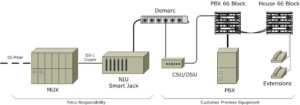
The smart jack is the handoff to the customer, it is the demarcation point. The smart jack allows for remote looping of the circuit, so that they can remotely check their provisioning of the line and circuit. It is how the telco provider checks to see if it is their problem or your problem. It is where your installation job will begin once they had delivered the circuit to you…
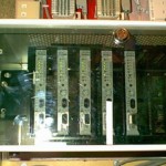
Smart jacks come in many different shapes, sizes and styles; they can be wall mount single units or banks like the one depicted in the diagram above. If you were to order a single DS1/T1 circuit you would most likely have a 4 wire shield cable coming in from the local CO or nearest MUX into a wall mounted unit. This unit is nothing more than a box with a single line card slid into the connector, although a lot of these units do at least two or four cards/circuits. The most common line card used today is the Westell SlimJack or Adtrans DS1 card, they can be found in any telco closet or PBX room today.
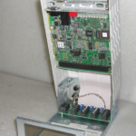
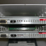
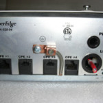
Another common installation is a bank of T1/DS1 cards; the unit is commonly mounted inside the MUX. The way the customer interfaces with it is a jack panel that will plug into the cage of DS1/T1 cards called the NIU, it does this with a parallel port looking connector that is prewired to the jack panel. The jack panel will have RJ-45 looking connectors called RJ-48C connectors with numbers corresponding to the line cards in the NIU/smart jack.
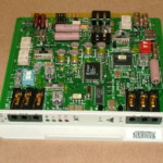
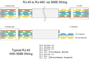
The RJ-48C or RJ-48X is the Demarc! The difference between an RJ-48C and an RJ-48X is; the RJ-48X has shorting blocks that short over to create a mechanical loopback at the female jack receptacle. The difference between an RJ-45 and RJ-48C is which wires are used. No matter what type of NIU / smart jack the telco installs, they will hand you off the DS1/T1 circuit thru an RJ-48C connector. So this is where you are responsible! So let’s educate ourselves on wiring.
So first let me state that if you are connecting a CSU/DSU to the RJ-48C you can use a standard network patch cable! It is straight thru cable and that is all you need, so if you are unsure TEST YOUR CABLE with the same network tester you always use. Generally you always want to use a CSU/DSU when connecting to a PBX although most PBXs do not require one; it is a good idea because the telco provider can remotely loop it and it provides a point of diagnostic. Most CSU/DSU units also allow manual looping bi-directionally to telco and to CPE.
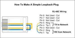
If the equipment is not next to the smartjack then you may need to take it out of the Demarc and run it over your “house wiring”. The house wiring is nothing more than a 50-pair or 25-pair cable that runs between two locations in your building. If that is the case then you will want to wire the RJ-48C as follows and punch it down on your house wiring. The reason is the 1 and 2 pin is used for RX Ring and Tip and the TX uses the 4 and 5 pin for Ring and Tip; so when they are punched down you can use the standard USOC wiring colors. So this way the RX Ring and Tip uses the first USOC colors of white-blue/blue and the TX Ring and Tip uses the second USOC colors of white-orange/orange.
Terminology
Central Office – The physical structure that holds the signaling equipment used to switch phone calls and generally make up the exchange. (NPA – Area Code and NXX – Exchange) Many COs together make up the LATA.
LATA – (Local Access Transport Area) is a term used in telcom to represent a geographic area that was created when AT&T broke up into smaller Baby Bells. The LATA is drawn around a market and is sometimes used for billing purposes and termination of phone numbers; generally this makes up the exchange.
POTS – (Plain Old Telephone Service) is voice grade communications line that is run to most all residential and businesses since the inception of the phone.
NIU – (Network Interface Unit) is the equipment that exposes the Demarcation point to the customer.
CPE – (Customer Premise Equipment) is the equipment that is owned by the customer that connects into the telephone network.
USOC – (Universal Services Ordering Code) is the specification set forth by Bell Systems as a universal way customers could connect to the public network. These codes, adopted in part by the FCC, Part 68, Subpart F, Section 68.502, are a series of Registered Jack (RJ) wiring configurations for telephone jacks that remain in use today.
PSTN – (Public Switched Telephone Network) also known as POTS, this is the network that a PBX would interface with to place calls or your typical phone at home.
Voice Network Speed Hierarchy

Signal   Carrier          Speed         DS0 Equivalents
DS0      T&R Copper Pair  64 kbps       1
DS1      T1 Copper Pairs  1.544 mbps    24
DS3      T3 Coax          44.736 mbps   672

STS-1    OC-1 Fiber       51.84 mbps    672
STS-3    OC-3 Fiber       155.52 mbps   2016
STS-12   OC-12 Fiber      622.08 mbps   8064
STS-48   OC-48 Fiber      2488.32 mbps  32256
STS-192  OC-192 Fiber     9953.28 mbps  129024
October 31st, 2010 at 8:04 pm
Running a T1 Data Circuit to computers. New install with 13 Computers, 7 Network Printers, and 1 Server, they all have network problems going out of the building. Can ping all IP Addresses in building thru the in-house switch, but going out of the building thru the same switch, PSU/DSU, and smart Jack won’t ping but time out. The phones are IP phones that run on same data circuit and I keep getting complaints on distant end of noisy and choppy conversations.
The incoming T1 is being carried on a single pair wire, but when the circuit comes out of the smart jack it is 2 pairs of wire. On the incoming pair there is 150 Volts DC on that line. Is this normal??? Is a single to 2 pair correct?
Please reply ASAP!!! At rdecker913@yahoo.com
November 1st, 2010 at 10:01 am
Sounds like a firewall is blocking PING, since the IP phones work and go out the connection. So I would focus my attention on the unit between the switch and the T1. As for conversations that are choppy and have distant end noise; this is a direct result of jitter which is the difference in latency between packets. Since you are suffering a performance problem I recommend:
Step One – Create a baseline analysis of the problem using a tool like pingtest.net and speedtest.net. I personally use pingtest.net to gauge WAN lines for VOIP, if you do not end up with a rating of A you have work to do.
Step Two – From the results of your analysis conclude if it is packet latency, packet loss or jitter from packet latency.
Packet loss – Remove components from your network like NAT boxes and keep testing – This method of diagnostic is called isolation, you want to isolate the problem until you find it.
Latency – Check protocols running over your T1 and ultimately you will need to prioritize your VOIP. Again isolate by removing all other computers and check it with just the computer plugged into the router.
As for the PING/ICMP problem I would do the same… Isolate the problem.
The 150volts sounds odd… Coming into the smartjack you should see a max of 48volts, however I have not researched that to end degree… You may have 150volts DC coming in to power the smartjack… I would have the smartjack checked for packet loss first from the provider, since that is the purpose of the smartjack.
January 5th, 2011 at 8:08 am
Question about smartjacks.
Are both RJ48C and RJ48X version’s capable of remote looping?
thanks.
January 5th, 2011 at 8:54 am
Randy,
The only difference between the RJ-48c and the RJ-48x is: the RJ-48x has a mechanical short bar that will mechanically loop the jack. However both have the ability to loop at the Network Interface Unit / Smart Jack itself. The RJ-48c or RJ-48x is the female jack for connectivity and the RJ-48x allows for looping all the way to the jack.
June 11th, 2011 at 8:52 am
I have a bad hum on unit, i checked from the jack to the switch repunched end to end know i have no dail tone what did i do wrong.
June 11th, 2011 at 5:26 pm
Sounds like the unit is either bad or the voice side has a shorted pair. If the hum was coming from the voice side then its shorted wires. Also check the common ground… which could cause a hum on the voice side… if you’re getting a hum from the unit it self my guess is a bad power supply.
June 18th, 2011 at 8:27 am
The hum is gone, checked the phone unit at another jack worked fine but at the switch (110 block) when i pull off the jumper i get dail tone with my butt set. I tone from end to end that feeds to another CO. And when you mean bad power supply is that from the phone unit it self?
February 22nd, 2012 at 5:45 am
Hi,
I understand that T1 copper cables uses 2 pairs (1&2 and 4&5), Right?
Now, you call T1 the piece of cable that is coming out of the CPE # to Smart Jack?
Why then, T1 / DS1 interface unit, ONLY need ONE pair to connect to outside carrier? In other words; One pair in, Two pairs out.
Thank you!
February 22nd, 2012 at 7:02 am
Carrier equipment will differ, although I haven’t seen it lately. Carriers will use a single pair to connect over the local loop to the equipment in the central office. The reason I haven’t seen it lately is because it introduces latency and VOIP application do not like it what so ever. The side you have the two pairs on if full duplex and one pair is for TX the other for RX. The side you have one pair is both TX and RX or half duplex. Again this is not a common practice anymore, but I’ve seen it when either carriers can’t get a full two pairs or the CLEC they lease the line from lets them. Either way, not ideal but it happens; usually in city installations.
February 28th, 2012 at 4:13 pm
what is the maximum wiring distance allowed coming from the smartjack to the CPE
February 28th, 2012 at 7:55 pm
I can say I’ve never had it answered intelligently, however I have run distances of over 1200 feet with no problems at all. It basically depends on the equipment and proper grounding of the equipment. I have seen Cisco documentation that states 6200 feet and seen many documents that state 1000 meters (generally ISDN)
In the particular installation where I extended the CPE 1200 feet we put in lightning arrestors at both ends, because it was one building to another building. All equipment is ground to earth grounds so that the potential of static differential between buildings doesn’t hurt the equipment. If it’s in the same building just make sure your grounded properly. Again the maximum distance is up to the equipment (both the providers and the customers), you’re best to call the equipment manufacturer.
March 27th, 2012 at 8:16 am
Hello Bohack.. I have installed AT&T T-1 and extended it to my location. Although I see a green CD light at the back of the router there seems to be an alarm as well which is why I am not connected. At the demarc I have standard 4 cable T-1 connector plugged into smartjack and terminated on a 66 block. I have extended that into my unit. At the CSU/DSU end I have terminated the T-1 extension on RJ-48X box and then used patch cord to the router.
Is it the wiring that is an issue ? or RJ48-x termination I dont seem to get it. I asked one of the t-1 install tech I found near the office and he suggested to reverse the polarity. Can you please suggest what to look for in this case ?
Thanks.
March 27th, 2012 at 9:20 am
I would recommend making a T1 loopback plug pin 1 to the 4 and 2 to the 5 see this article for a visual. Take that plug and connected it to the back of the router… If the alarm lights go out, you will need to retrace your wiring to make sure that you do not have crossed lines. You will also need to check if your encoding on the line is right, in other words what the network is sending you and what you are expecting to see.
March 27th, 2012 at 5:41 pm
I have never got a good answer on T1 extensions either, but I have 1 going 4000 ft thru farm cables. Best answer I got was the smart jacks and the equipment self compensate back to zero db. In the old days there was dipswitches on the Sjack. For the novice, if you make your extensions like a cat5-b cable, they work. Everything on the customer side needs 2 pairs. And yes the phone company uses high voltages to get them there, on 1 if they are close, s for longer distances.
March 27th, 2012 at 8:11 pm
Thanx for the comments and I agree that the phone company uses high voltage to get them there. I just ran into a VOIP system today that I had to up the battery voltage on because the alarm panel didn’t see the presence of a phone line. P.S. I added your website to the URL comments. NEC We have a 2400 IPX and it is like rocket science to configure a LENS.
August 19th, 2012 at 10:40 pm
Just wanted to comment that you did a great job explaining to us the basics of Telecom. I just started a position that requires Telecom administration (something I had no clue I was signing up for) and was happy to come across such a great blog post.
Signed,
A 23 year old Senior Service Center Analyst / Field Engineer
August 22nd, 2012 at 12:21 pm
Glad I could help… I’ve been doing WAN work for the past decade and it always fascinates me. It’s actually really complicated, but the service tech make it seem so simple.
September 10th, 2012 at 6:22 am
If I want to build a 4-wire DS-1 RJ48 cable from a switch to switch, what would be the pinout? 1 to 2 and 4 to 5 I’m assuming? the configuration is a switch to patch panel to switch?
any answers?
September 18th, 2012 at 10:35 am
I appreciate the clarity presented in your explanation. I have one concern that you touched on, yet seem to make an asumption… Please describe acceptable wire types (Cat3, Cat5, Cat6, single pair, four pair, twenty-five pair, fifty/one-hundred pair etc., etc.) to be utilized in the “house” portion of the T1.
More specifically, what are the limits to the various horizontal and vertical house cables available within many buildings with multiple tennants and a central Minimun Point Of Entry- since the spectrum of cable types is limited only by the local supplier and/or installer choice?
The response from most T1 vendors is simple, “well just run a single IW, 4pair, Cat5”. This concerns me as I survey the vast amount of copper embedded in most sites and wonder what the correct bench mark is.
Thanks.
September 18th, 2012 at 10:51 am
You can use Cat 5, Cat 6 even Cat 3… the data rate on the cable is extremely slow compared to 100mb/s in a LAN environment. However to be correct the wire recommended to use on installation of a T1 connection is 2 pair shielded twisted pair. Preferably one pair orange and the other pair blue. T1 cable is suppose to be low capacitance with double shielding on the cable with a ground. I usually use Cat 5 for my installs on campus, because the Belden 7838A is 90c per foot and the Cat 5 is 20c per foot. If you want to do it to the “T” order a spool of the 7838A http://www.belden.com/techdatas/metric/7838A.pdf. My supplier only sell the roll of 1000 foot, however maybe you’ll have luck ordering just what you need.
September 18th, 2012 at 10:57 am
The following will give you what I call a T1 crossover. I use it all the time in lab environments. Just make sure one side provides clocking.
1 on side a to the 4 on side b
2 on side a to the 5 on side b
4 on side a to the 1 on side b
5 on side a to the 2 on side b