How To Solve Common Problems with VOIP and Fire Alarm Systems Dialing Out – Part 3
In the part two I covered transmit and receive volume and DTMF Relay. In this last part we roll up our sleeves and look at some tcpdumps in Wireshark. This is how we can identify issues and remedy them with the past two articles.
First we need to get the dump and if you have your ATA directly connected to a firewall, you may need to put a hub in and capture the old fashion way or span a port. If you are using a Linux based firewall you can always use the tcpdump command. I run all of my ATAs to a central Linux Asterisk box. So no matter how you get the dump, you need to capture the packets.
Assuming you are on a Linux box either spanned off a port or sniffing in promiscuous mode on a hub, you need the proper command to capture the traffic. Using the tcpdump command is the easiest, use the command below to capture a dump that you can view in Wireshark.
tcpdump -i eth0 -s 1500 -w ~/dump.cap
The preceding command will listen on interface eth0. To find your interface you will initiate an “ifconfig –a”, to list your interfaces. It will capture 1500 bytes of data rather than the 68 bytes by default. It will dump it to your home directory as the file named dump.cap. To get it over to a windows box I recommend using winscp.
Voice Quality
If you’re lucky enough to be working with an Adtran Total Access AOS ATA router then the command below will work for you. If not other manufacturers like Cisco have similar commands. After the call has been placed you need to analyze the quality, you can do so with the following command:
Adtran #sh voice quality-stats
      Start                   Lost Discard Delay
ID Time From To Duration Codec Pkts Pkts Avg Max

--------------------------------------------------------------------------------

130 10:38 AM 4125551234 4125551212 5:43 G711u 0 0 50 50
131 10:45 AM 4125551234 4125551212 2:43 G711u 0 0 50 50
132 10:48 AM 4125551234 4125551212 8:16 G711u 5291 0 50 50
133 10:56 AM 4125551234 4125551212 4:49 G711u 27097 0 80 50
134 11:02 AM 4125551234 4125551212 1:03 G711u 0 0 50 50
The output will not show all calls just the most recent in the buffer. There is plenty of information in the dump above on our calls. The first being the codec used for the placement of the call. If the particular call is data and is going over g729 it will fail. If this is the case then it is recommended to configure the “modem-passthrough” command from part 1 of this series. Because it will force data calls to switch to the g711u or ulaw codec.
Another great piece of information is the lost packets, which are not really lost. They just show up to the destination out of order and inject latency to the RTP protocol. Again the “modem-passthrough” will help with this, as well as putting on a newer version of AOS. Some of these problems have been solved in later releases that have tuned the DSP or Digital Signal Processor.
You can also see the delay of the packets which are directly attributed to the jitter buffer. Again the “modem-passthrough” will help with this, as well as putting on a newer version of AOS.
Wireshark can also give you an over view of problems. To get the important information out, use the tcpdump and load it into Wireshark. Once loaded in, click on “Telephony”, then “RTP”, then “Show All Steams”
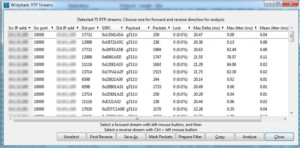
This will show you direction of flow from source IP and port to destination IP and port. It will also display the codec used for the call of either g729 or g711 ulaw. Most importantly it will show you the quality of lost packets, that never showed up on the other side. Your max delta should always be about 20ms. Lastly and not least is the max jitter and mean or average jitter. The lower this is to 0ms the better the call quality. If these are off by too much the Internet connection might be too poor for VOIP let alone data over VOIP.
TX and RX Gain
Although we can use Wireshark and look down to the packet level, I cannot stress the importance of a line man’s butt set to listen to the call. Saying that… We can analyze the packet for improper or low volume. Looking at the VOIP call with Wireshark and playing the audio back will give us a comparison to what we heard. In conjunction with the “tx-gain” and “rx-gain” commands we can see an actual difference in amplitude. My recommendation is to save your dumps with dates and times for comparison. To decode the RTP streams click on “Telephony”, then on “VoIP Calls”, find the call you want to view and select it, then click “Player”, then “Decode”. This will show both sides of the call, so to listen to the converged call you will need to select both, then click “Play”.
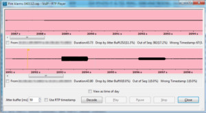
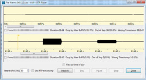
As you can see in the pictures above the pink capture has lower amplitude than the yellow capture. This is because these are two different units that I captured on, one having a higher RX and TX gain.
DTMF Relay
In the part two of this series I explain DTMF relay in detail. Since most alarm panels transmit data via DTMF tones, we can see the DTMF out of band in action here as well as the bleed over. The yellow Ws are wrong timestamps, which proves that the DTMF relay strips the DTMFs out leaving a jump in timestamps.
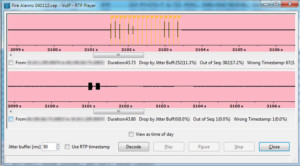
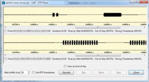
The pink capture shows the wrong timestamps and the bleed over of the DTMF tones. The yellow capture is after we initiate the “rtp dtmf-relay inband” command. We can now see the DTMF tones being sent in band of the RTP stream.
Wireshark is like any other tool, it will not fix the problem it will identify the problem. Ultimately you will need to fix the problem being the technician. However understanding what is going on at the packet level, helps us to ultimately fix the problem that can be seen.
As always if you found this article to be useful either donate or visit some of my sponsors so I can continue to create these articles.